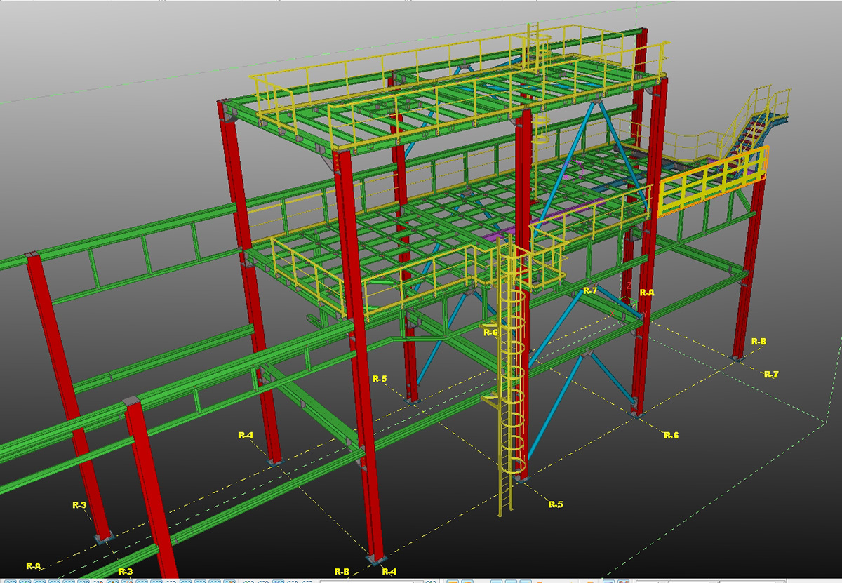
A pipe rack can support piping, instruments, cable trays, and other in-process facilities. The minimum clearance needed for the rack to operate determines the pipe rack height. Although this may sound obscure, a pipe rack has various uses.
Pipe Rack Structural Drawings
The minimum clearance needed for the rack to operate as intended determines the height. Although this may sound obscure, a pipe rack has various uses. The pipe rack is typically just a device to keep the pipes off the ground in agricultural settings.
Unwanted exterior corrosion may occur if the exposed pipe touches the ground. In this case, the pipe rack should be built with steps that can pass through the piping where accessibility is needed. That’s the first step in Pipe Rack Structural Drawings.
- Suppose the pipe rack is located in a building, refinery, or any area where there will be vehicular traffic.
- In that case, the pipe’s elevation at the bottom should be greater than the highest vehicle that will pass underneath it.
- A pipe rack’s height can also be determined by the minimum overhead clearance needed for the lowest level of piping that passes beneath the rack.
- Depending on the requirements of your project, this is normally between 12 and 15 feet.
- Consider a system in which laterals run east-west direction, and a pipe rack runs north-south. Due to equipment constraints, the lateral pipe rack must be exactly 12′ above grade.
- If 12 is the largest average line size, “NPS, then two 90-degree ells will be necessary to switch from the E-W rack to the N-S rack.
- Two 90s will result in an elevation increase of 36 since each long radius ell has a height 1.5 times the nominal diameter “. In this instance, the N-S pipe rack height will be 15′ from grade, while the E-W pipe rack height is 12′ from grade.
WIDTH OF A PIPE RACK
The width of a pipe rack can be calculated in several different ways. A piping transposition schematic made from P&IDs and a rough equipment layout are often created during the plot plan preparation process. In a transposition drawing, lines from a particular set of P&IDs are used and placed in the location that will house the pipe rack. For more details, see the transposition graphic.
- The designer must properly space the lines after deciding how many lines will be in the rack.
- Get the two pipes’ respective exterior diameters that are opposite one another. Include insulation or a heat barrier in the outside diameter if there is one.
- Use the outer diameter of any flanges if there are any. Figure out the shortest distance between both pipes. Use 2″ spacing if the room is at a premium.
PIPE RACK ORDERING
The designer will examine crowded areas after the piping rack has been put out and work to reduce the number of elbows & fittings. At the very least, every elbow, fitting, and flange raises the price of a weld. Reducing the amount of welds results in significant construction expenses for large-diameter pipes.
SPACE FOR PIPE SUPPORT
The size of the pipes, the load they are carrying, seismic restrictions, laws, and regulations all impact how far apart supports must be placed. An engineer with structural expertise decides this. The engineer must be informed of any design specifications, such as the necessity for additional width to accommodate cars.
Last Thoughts
If there is room when creating the design. USE it. Installing a bigger rack today is much less expensive than expanding it later. Avoid areas where humidity can collect if there are gas lines. Think about tilting the pipe racks if the line needs to be sloped.
Ensure that there are sufficient vertical clearances for all anticipated traffic. This can include forklifts, trucks, cranes, and emergency vehicles. When creating the pipe rack, think about upgrades in the future. A PLC under a rack might eventually need to be taken out. Make that the area is appropriate for this activity.


